01 Nov 2016
Every compression algorithm covered herein is lossy in nature, so how we measure accuracy is critically important. Measured deviation from source data needs to be representative of the visual differences observed.
It is also important to compare algorithms against each other. It is surprising to learn that many academic papers on this topic use varying error metrics making meaningful comparison quite difficult.
Error measuring needs to meet a number of important criteria:
- Account for the hierarchical nature the data since errors accumulate down the hierarchy when using local space transforms
- Account for errors in all three tracks for every bone
- Account for the fact that visual mesh almost never overlaps with its skeleton and the further away a vertex is from its bone the larger the error will end up being
Object Space vs Local Space
For compression reasons, transforms and blending poses are usually stored in local space. However, due to the hierarchical nature, a small error on a parent bone could end up causing a much larger error on a child’s bone further down. For this reason, errors are best measured in object space.
Surprisingly, it is quite common for compression algorithms to use local space instead. Error is measured using linear key reduction and curve fitting algorithms.
Approximating the Visual Error
Since a skeleton is generally never directly visible errors are visible on the visual mesh instead. This means the most accurate way to measure errors is to perform skinning for every keyframe and comparing vertices before and after compression.
Sadly, this would be terribly slow even with help from the GPU in many instances.
Instead, we can use virtual or fake vertices at a fixed distance from each bone. This is both intuitive and easy to achieve: for every object space bone transform we simply apply the transform to a local vertex position. For example, a vertex in local space of a bone at a fixed offset of 10cm will end up in object space with the object space bone transform applied. This step is done with both the source animation and the compressed animation so we can compare the distance between the two transformed vertices to measure error.
For this to work we need to use two virtual vertices per bone and they must be orthogonal to each other. Otherwise, if our single vertex happens to be co-linear with the bone’s rotation axis, the error could end up being less visible or entirely invisible. For this reason, two vertices are used with the maximum error delta. In practice, we would use something like vec3(0, 0, distance) and vec3(0, distance, 0).
This properly takes into account all three bone tracks and it approximately takes into account the fact that the visual mesh is always some distance away from the skeleton.
Which virtual distance you use is important. A virtual distance much smaller than the distance of real vertices the error might end up being visible since error increases with distance for rotation and scale. If the distance is much larger we might end up retaining more accuracy than we otherwise need.
For most character bones a distance in the range of 2-10cm makes sense. Special bones like the root and camera might require higher accuracy and as such should probably use a distance closer to 1-10m.
Large animated objects also occasionally benefit from vertex to bone distances of 1-10m and either need extra bones added to reduce maximum distance, or the virtual distance needs to be adjusted correspondingly.
It’s also worth mentioning that we could probably extract the furthest skinned vertex per bone from the visual mesh and use that instead but keep in mind some bones might not have skinned vertices such as the root and camera bones.
Conclusion
Accuracy is modified using a single intuitive number, the virtual vertex distance and is measured with a single value, object space distance.
Both Unity and Unreal measure accuracy in ways that are sub-optimal and fail to take into account all three properties outlined above. From what I have seen their techniques are also representative of a lot of game engines out there. Future posts will explore the solutions those game engines provide.
A number of compression algorithms use the error metric function to attempt to converge on a solution like linear key reduction, for example. If metrics are imprecise or poorly represent true error it is very likely that will be reflected in the end result. Many linear key reduction algorithms use a local space error metric which sometimes leads to important keys being removed from distant children of the point of error. For example, a pelvis key being removed can translate into a large error at the fingertip. The typical way to combat this side-effect is to use overly conservative error thresholds but this translates directly in the memory footprint increasing.
See also: Dominance based error estimation
Up next: Constant Tracks
Back to table of contents
27 Oct 2016
Animation clips more or less always boil down to the same thing: a series of animated tracks. There might also be other pre-processed data (such as the total root displacement, etc.) but we won’t concern ourselves with this since their impact on compression is usually limited. Instead, we will focus on bone transform tracks: rotation, translation, and scale.
While we can represent all three tracks within a single affine 4x4 matrix, for compression purposes it is usually best to treat them separately. For one thing, a full column of the matrix doesn’t need to be compressed as it never changes and we can typically encode the rotation in a form much more compact than a 3x3 matrix.
Rotation
Rotations in general can be represented by many forms and choosing an appropriate representation is important for reducing our memory footprint while maintaining high accuracy.
Common representations include:
- 3x3 matrix (9 float values)
- wasteful, don’t use this for compression…
- quaternion (4 float values)
- high accuracy, fast decompression, a bit larger than the others
- quaternion with dropped W component (3 float values)
- W can be reconstructed with a square root, the quaternion can be flipped to keep it in the positive hemisphere
- quaternion with dropped largest component (3 float values + 2 bit)
- similar to dropping W, but offers higher accuracy
- quaternion logarithm (3 float values)
- this is equivalent to the rotation axis multiplied by the rotation angle around our axis
- axis & angle (4 float values)
- a bit larger than most alternatives
- polar axis & angle (3 float values)
- high accuracy but slower decompression
- Euler angles (3 float values)
- best avoided due to Gimbal lock issues near the poles if quaternions are expected at runtime
Which representation is best depends in large part on what the animation runtime uses internally for blending clips. There are three common formats used at runtime:
- 4x4 affine matrix
- quaternion
- quaternion logarithm
If the compressed format doesn’t match the runtime format, a conversion will be required and it has an associated cost (typically sin & cos are involved).
Some formats offer higher accuracy than others at an equal number of bits. A separate post will go further in depth about their various error/size metrics.
Generally speaking, the formats with 3 float values are a good starting point to build compression on. Which of them you use might not have a very dramatic impact on the resulting memory footprint but I could be wrong. Obviously, using a format with 4 floats or more will result in an increased memory footprint but beyond that, it might not matter all that much.
Rotations are often animated but their range of motion is typically fairly small in any given clip and the total range is bounded by the unit sphere (-PI/PI for angles, and -1/+1 for axis/quaternion components).
Because rotations work on the unit sphere, the error needs to be measured on the circumference traced by the associated children. For example, if I have an error of 1 degree on my parent bone rotation, the error at the position of a short child bone will be less than that of a longer child bone: the arc length formed by a 1 degree rotation depends on the sphere radius. This needs to be taken into account by our error measuring function as we will see later in a separate post.
Translation
Translations are typically encoded as 3 floats. Translations are generally not animated except for a few bones such as the pelvis. They tend to be constant and often match the bind pose translation. Sadly, they are typically not bounded as some bones can be animated in world space (e.g. root bone in a cinematic) or they can move very far from their parent bone (e.g. camera).
They could also be encoded as an axis and a length (4 floats) and in its polar equivalent (3 floats). Whether the polar form is a better tradeoff or not, I cannot say at this time without measuring the impact on the accuracy, memory footprint, and decompression speed. It might not work out so great for very large translation values (e.g. world space).
Scale
Scale is not common nor is it typical in character animation but it does turn up. For our purposes we will only consider non-uniform scaling with 3 floats but uniform scaling with a single float would be a natural extension.
Scale is very rarely animated and as such it will generally match the bind pose scale. Unfortunately, the range of possible values is unbounded with the minor exception that a scale of 0.0 is generally invalid.
Because the scale affects the rotation part of a 4x4 affine matrix, the same issues pertaining to the error are present.
Similar to translations, it might be possible to encode it in axis/length form but whether or not this is a good idea remains unclear to me at this time.
The skeleton hierarchy
Due to its hierarchical nature, we can infer a number of properties about our data:
- In local space, bones higher up in the hierarchy contribute more to the overall error
- In local space, a parent bone and its children can be animated independently, leading to improved compression but reduced accuracy since any error will accumulate down the hierarchy
- In object space, if a parent is animated, all children will in turn be animated as well but this also means their error does not propagate
As we will see in a later post, these properties can be leveraged to reduce our overall error.
Bone velocity
Generally, we will only compress sampled keys from our original source sequence and as such the velocity information is partially lost. However, it remains relevant for a number of reasons:
- High velocity sequences (or moments) will typically compress poorly and these are quite common when they come from an offline simulation (e.g. cloth or hair simulation) or motion capture (e.g. facial animation).
- Smooth and low velocity clips will generally compress best and thankfully these are also the most common. Most hand authored sequences will fall in this category.
- Most character animation sequences have low velocity motion for most bones (they move slowly and smoothly)
- Many bone tracks have no velocity due to the fact that they are constant and it is also common for bones to be animated only for certain parts of a clip
To properly adapt to these conditions, our compression algorithm needs to be adaptive in nature: it needs to use more bits when they are needed for high velocity moments, and use fewer bits when they aren’t needed. As we will see later, there are various techniques to tackle this.
See also Animation Data in Numbers
Up next: Measuring Accuracy
Back to table of contents
26 Oct 2016
Animation Sequence or Clip
Central to character animation is our animation sequence. These are also commonly called animation clips and I will use both terms interchangeably.
A clip is composed of several bones and standalone tracks. This post will not focus on standalone tracks since they can typically be represented as fake bones and regardless, all the techniques we will cover could be used to compress them as well as a natural extension.
Skeleton
Our character animation sequences will always play back over a rigid skeleton. The skeleton defines a number of bones and their hierarchical relationship (parent/child).
A skeleton has a well defined bind pose. The bind pose represents the default reference pose of the skeleton. For example, the pelvis bone would have a bind pose with a fixed translation offset of 60cm above the ground. The first spine bone would have a small offset above the parent pelvis bone, etc.
A skeleton has a root bone. The root bone is the bone highest in the hierarchy on which all other bones are parented. This is typically the bone that is animated to move characters about the world when the motion is animation driven.
Bone
A bone is commonly composed of at least 2 tracks: rotation and translation. The next post will go into further details about how these are represented in the data.
Also very common is for bones to have a scale value associated. When it is present, bones have a 3rd scale track.
All bones have exactly one parent bone (except the root bone which has none) and optional children.
A bone transform can be represented in a number of ways but for our intents and purposes, we can assume it is a 4x4 affine matrix. These support rotation, translation, and non-uniform scale.
A bone transform can be either in object space or local space.
Track
A track is composed of 1+ keys. All tracks in a raw sequence will have the same number of keys. A sequence with a single key represents a static pose and consequently has an effective length in time of 0 seconds.
Track key
A track key is composed of 1+ components. For example, a translation track would generally have 3 components: X, Y, and Z.
Key component
A key component is a 32 bit float value in its raw form. In practice, standalone tracks could have any value or type (bool, int, etc.) but we will mostly focus on rotation, translation, and scale in this series and these will all use floats.
Key interpolation
Key interpolation is the act of taking two neighbour keys and interpolating a new key at some time T in between. For example, if I have a key at time 0.0s and another at time 0.5s, I can trivially reconstruct a key at time 0.25s by interpolating my two keys.
Because video games are realtime, it is very rare for the game to sync up perfectly with animation sequences, as such nearly every frame will end up interpolating between 2 keys. Consequently, when we sample our clips for playback, we will typically always sample 2 keys to interpolate in between.
Generally speaking, the interpolation will always be linear even for rotations. This is typically safe since keys are assumed to be somewhat close to one another such that linear interpolation will correspond approximately to the shortest path.
Note that some algorithms perform this interpolation implicitly when you sample them: linear key reduction, curve fitting, etc.
Object space
Bone transforms in object space are relative to the whole skeleton. For certain animation clips such as cinematics, they are sometimes animated in world space in which case object space will correspond to world space. When this distinction is relevant, we will explicitly mention it.
Local space
Bone transforms in local space are relative to their parent bone. For the root bone, the local space is equivalent to the object space since it has no parent.
Converting from local space to object space entails multiplying the object space transform of our parent bone by the local space transform of our current bone. Converting from object space to local space is the opposite and requires multiplying the inverse object space transform of our parent bone by the object space transform of our current bone.
Rotation
A rotation represents an orientation at a given point in time. It can be represented in many ways but the two most common are 3x3 matrices and quaternions. Other format exist and will be covered to some extent in future posts.
Translation
A translation represents an offset at a given point in time. It is typically represented at a vector with 3 components.
Scale
A scale is composed of either a single scalar value or a vector with 3 components. The later is used to support non-uniform scaling in which skew and shear are possible. For our purposes, scale will always be a vector with 3 components.
Frame
A frame represents a unit of time. Most games are played at 30 frames per second (FPS) as such every frame has a length of time equal to 1.0s / 30.0 = 0.03333s.
A clip with 2 keys consequently has 1 unit of time that elapses in between. If the first key is at 0.0s and the second key is at 0.5s, we can reconstruct the key position at any time in between by linearly interpolating our keys. A clip with 11 keys, has 10 frames, etc.
The frame rate of the game does need to match the sample rate of animation clips.
Note that in the literature, the term ‘frame’ is sometimes used to mean a transform (e.g. frame of reference).
Sample rate
The sample rate dictates the frequency at which the keys are sampled in the original raw clip. A sample rate of 30 frames per second translates in 1 second of time being divided into 30 individual frames. For a sequence with a length of 1 second, the resulting clip will have 30 frames and 31 keys.
If our game runs at a higher frame rate than our sequence sample rate (e.g. 60 FPS), we will end up interpolating between 2 keys twice as much. If in turn our games runs slower than our sample rate (e.g. 15 FPS), some keys will be skipped during playback.
Common sample rates are: 15 FPS, 20 FPS, and 30 FPS.
Most games run at a frame rate of 30 FPS or 60 FPS.
An affine transform is a 4x4 matrix that can represent simultaneously rotation, translation, and non-uniform scaling.
Quaternion
A quaternion is a 4D complex number that can efficiently and conveniently represent a rotation in 3D space. We will not go further in depth but I will do my best to explain the relevant bits as we encounter them. Since we will mostly use them for storage, we will do very little math involving them.
The most important thing to know about them is that for a quaternion to represent a rotation, it must be normalized (unit length). And obviously, it is made up of 4 scalar float numbers.
Up next: Animation Data
Back to table of contents
25 Oct 2016
This post is meant as a preface to explain the overall context of what is character animation, how we use it, and why it needs special consideration.
This series of posts will only cover the compression aspect of animation data, we will not look into everything else that goes into writing an animation runtime library such as Morpheme.
Modern character animation
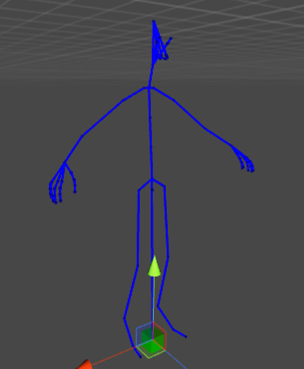
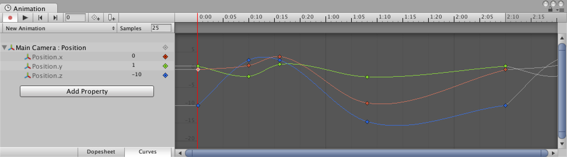
For the purpose of this series, we will only refer to character animation sequences that play back over a rigid skeleton (also called a rig). In Maya (and other similar products), an animator will typically author the animation sequence from a set of curves by manipulating the skeleton to achieve the desired motion.
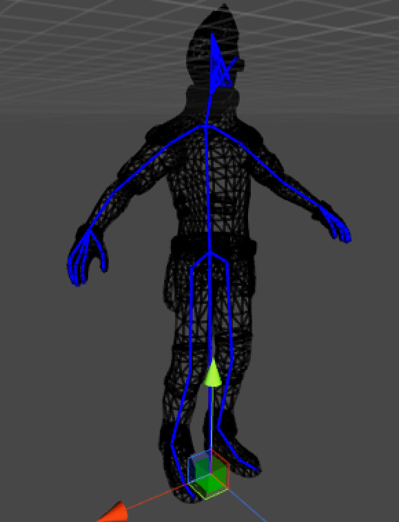
This information is used at runtime to animate the rigid skeleton which in turn deforms the visual mesh bound to it. Note that animation sequences can be authored in 3 main ways: by hand, from motion capture, or procedurally (for example, a cloth simulation).
Central to all this is our rigid skeleton. The skeleton is composed of a number of bones, typically in the range of 100-200 for main characters (but this number can be much larger, up to 1000 in some cases). Some of these will almost always be animated (such as the pelvis), some are animated procedurally at runtime and thus never authored, while others are only animated in a small subset of animations such as facial bones.
The actual process to generate the final skeleton pose will vary but it generally involves blending a number of animation sequences together. The number of poses blended will vary greatly at runtime, and for a main character it can often range from 6 to 20 poses. Although an interesting topic, we will not go into further detail.
The final visual mesh deformation process is commonly referred to as ‘skinning’. Depending on the video game engine, skinning is typically done either by interpolating 4x4 matrices or dual quaternions. The former is the most common but can yield some artifacts while the later approach is the mathematically correct way to do skinning. Both have their pros and cons but we will not go further into detail since it is not immediately relevant to our topic at hand.
How is it used in AAA video games?
For a long time now (at least since the original PlayStation), 3D character animation has been used by a large array of video game titles. Over time the techniques used to author the animation sequences have evolved and the amount of content has gradually crept up. Today, it isn’t unusual for a AAA video game to have several thousands of individual character animations.
Animation sequences are used for all sort of things beyond just animating characters: they can animate cameras, vegetation, animals or critters, objects (e.g. door, chest), etc.
As a result of this, it is not unusual to end up having between 20-200MB worth of animations at runtime. On disk, the size is of course even larger.
Its unique requirements
To generate a single image (or frame), it is not uncommon to end up sampling over 100 animation sequences. As such, it is critically important for this operation to be very fast. Typically on a modern console, we are targeting 50-100us or lower to sample a single sequence.
Due to the large amount of animation sequences, it is also very important for their size to remain small. This is both important on disk, which impacts our streaming speed, and in memory, which impacts the maximum amount of sequences we can hold.
As we will see later, not all animation sequences are created equal, as some will require higher accuracy than others.
These things must all be taken into account when designing or selecting a compression algorithm. The compression algorithms we will be discussing will all be lossy in nature as that is the most common industry practice.
Note: All images taken from Unity 5
Up next: Terminology
Back to table of contents
21 Oct 2016
Character animation compression is an exotic topic that seems to need to be re-approached only about once per decade. Over the course of 2016 I’ve been developing a novel twist to an older technique and I was lucky enough to be invited to talk about it at the 2017 Game Developers Conference (GDC). This gave me the sufficient motivation to write this series.
The amount of material available regarding animation compression is surprisingly thin and often poorly detailed. My hope for this series is to serve as a reference for anyone looking to improve upon or implement efficient character animation compression techniques.
Each post is self-contained and detailed enough to be approachable to a wide audience.
Table of Contents
ACL: An open source solution
My answer to the lack of open source implementations of the above algorithms and topics has prompted me to start my own. See all the code and much more over on GitHub for the Animation Compression Library as well as its Unreal Engine plugin!